16. La Ganancia Parcial.

En el capítulo anterior hablábamos de que somos capaces de intervenir en la amplitud de los ecos para poner la imagen más brillante o menos brillante, de modo general, es decir, en toda la pantalla, pero además te cuento hoy que somos capaces de intervenir en esa amplitud de forma parcial, según la zona de la pantalla que me interese, con este ajuste ecográfico que se llama «Ganancia Parcial» o TGC (compensación tiempo ganancia).

La ganancia parcial es un ajuste ecográfico donde 8 potenciómetros se reparten el brillo de la pantalla en 8 zonas diferentes de superficial a profundo, de modo que soy capaz de potenciar los ecos de retorno producidos en las interfases más profundas (débiles por la atenuación producida por la distancia) para que se «vean» igual de bien, que los ecos de retorno mas superficiales, que son «más fuertes»… Me explico, los ecos de retorno profundo son más débiles que los más superficiales, lógico, porque la energía tiene que recorrer más espacio y se debilita, yo puedo «ecualizar», reforzar esos ecos de retorno profundos para que lleguen mejor al transductor.

Si estoy hablando con una persona a 2 metros la oiré mejor que si hablo con ella a 20 metros, en este caso, tendremos que hablar más alto a 20 metros que a 2, esto es lo que hago con la TGC, elevar el volumen de los ecos de retorno lejanos para oírlos mejor.

In the previous chapter we talked about how we are able to intervene in the amplitude of the echoes to make the image brighter or less bright, in a general way, that is, in the whole screen, but I also tell you today that we are able to intervene in that amplitude of partial form, according to the area of ​​the screen that interests me, with this ultrasound adjustment called «Partial Gain» or TGC (compensation time gain). The partial gain is an echographic adjustment where 8 potentiometers share the brightness of the screen in 8 different shallow to deep zones, so that I am able to boost the return echoes produced in the deeper interfaces (weak by the attenuation produced by distance) so that they «look» just as well, as the more superficial return echoes, which are «stronger» … I mean, the deep return echoes are weaker than the shallower ones, logical, because the Energy has to travel more space and weakens, I can «equalize», reinforce those deep return echoes so they get better to the transducer. If I am talking to a person at 2 meters I will hear it better than if I talk to her at 20 meters, in this case, we will have to talk higher at 20 meters than at 2 meters, this is what I do with the TGC, raise the volume of the distant echoes of return to hear them better.
Potenciómetros TGC.

En la imagen anterior ves marcado con el número 3 una serie de botones escalados y en cifra de 8. El superior corresponderá a la parte más superficial de la imagen, la más cercana al transductor, y el inferior a la parte más alejada del transductor, la más profunda en la imagen. Los 8 se reparten así toda la pantalla, el 4 y el 5 potenciómetro, así conocidos cada botón, serán la parte central de la imagen.

Si movemos los potenciómetros a la izquierda oscurecemos la imagen, si lo hacemos a la derecha la haremos brillar más en la región de la imagen correspondiente al potenciómetro que movamos…Basta de literatura, ejemplos…

In the previous image you see marked with the number 3 a series of buttons scaled and in figure of 8. The superior will correspond to the most superficial part of the image, the closest to the transducer, and the inferior to the furthest part of the transducer, the deepest in the image. The 8 are distributed so the entire screen, 4 and 5 potentiometer, well known each button, will be the central part of the image. If we move the potentiometers to the left we darken the image, if we do it to the right we will make it shine more in the region of the image corresponding to the potentiometer that we move … Enough of literature, examples …

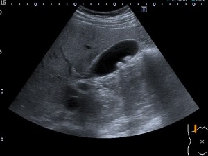
En estas imágenes anteriores observamos una imagen correctamente realizada en función de la alineación correcta de los potenciómetros de la TGC, que si observas, están ligeramente oblicuados a la derecha para que en la parte más profunda de la imagen los ecos de retorno sean reforzados…

In these previous images we see an image correctly made based on the correct alignment of the potentiometers of the TGC, which if observed, are slightly oblique to the right so that in the deepest part of the image the return echoes are reinforced

Si realizo mal la técnica y alineo mal los potenciómetros 4 y 5 y los llevo a la izquierda dejaré en negro y sin información, la parte central de la imagen, tal como reflejan estas dos últimas imágenes.

Bien, para resumir…La TGC es la ganancia selectiva a diferentes profundidades para minimizar los efectos de la atenuación sobre la imagen. El ajuste de las ganancias conllevará un cambio en la imagen.Es un ajuste dependiente del operador que maneje dicho equipo, en nuestro caso, del Técnico de Rayos, responsable por tanto de la consecución de una imagen perfecta y diagnóstica.

Este ajuste siempre ha estado en la botonera, pero los equipos más modernos lo tienen integrado en su aspecto digital, funcionando exactamente igual. En esta imagen que ves a continuación y señalado con una fecha en rojo, ves la TGC en la pantalla táctil del equipo, cada vez más habitual, y no en la botonera…muy típico también de los equipos de ecografía portátiles, eso sí siempre dependiendo de cada marca comercial.

If I make the wrong technique and I align the potentiometers 4 and 5 wrongly and I take them to the left, I will leave the central part of the image in black and without information, as these last two images reflect. Well, to summarize … The TGC is the selective gain at different depths to minimize the effects of attenuation on the image. The adjustment of the gains will entail a change in the image. It is a dependent adjustment of the operator that manages said equipment, in our case, of the Rays Technician, responsible therefore for the achievement of a perfect and diagnostic image. This adjustment has always been in the keypad, but the most modern equipment has it integrated in its digital aspect, working exactly the same. In this image that you see below and marked with a date in red, you see the TGC on the touch screen of the equipment, more and more usual, and not in the keypad … very typical also of portable ultrasound equipment, yes always depending on each commercial brand.
TGC digital.


15. La Ganancia General.

En el botón 2D encontramos otra función vital además de la representación de la imagen en 2 dimensiones, a la que accedemos presionando este botón.

Encontramos que normalmente este botón tiene la capacidad de girar como una rueda y así intervenimos en el brillo de la imagen de manera global en la pantalla. Esta otra función del botón 2D es la llamada «Ganancia General» o «Gain» y la podemos definir como la capacidad que tenemos de modificar la amplitud del eco (magnitud de onda ultrasónica), resultando una imagen más o menos brillante. Los cambios de la ganancia general afectan a toda la imagen por igual. Dependerá y tendrá que ser adaptada a las características de cada paciente.

Es como si estás escuchando tu programa favorito de la televisión, pero no lo oyes bien y subes el volumen del aparato para poder escuchar correctamente…

In the 2D button we find another vital function besides the representation of the image in 2 dimensions, which we access by pressing this button. We find that normally this button has the ability to rotate like a wheel and so we intervene in the brightness of the image globally on the screen. This other function of the 2D button is called «General Gain» or «Gain» and we can define it as the ability we have to modify the amplitude of the echo (ultrasonic wave magnitude), resulting in a more or less bright image. Changes in the general gain affect the entire image equally. It will depend and it will have to be adapted to the characteristics of each patient. It’s as if you’re listening to your favorite TV show, but you do not hear it well and you raise the volume of the device to be able to listen correctly …
Marca 1
Marca 2

En la marca 1 solo podemos controlar la ganancia general en el botón 2D, en la marca 2 podemos hacerlo en 2D y además en la rueda central que rodea el track ball y que está marcado con la palabra «gain».

La ganancia general interviene por tanto sobre los eco recibidos, es decir, sobre los ecos de retorno, y solo sobre ellos. En la imagen vamos a ver que lo que estamos haciendo al manejar la ganancia general, es intervenir sobre el brillo de la imagen de manera global, como hemos dicho antes, pero quiero que lo veas en imágenes…

In the 1 mark we can only control the general gain in the 2D button, in the 2 mark we can do it in 2D and also in the central wheel that surrounds the track ball and that is marked with the word «gain». The general gain therefore intervenes on the echoes received, that is, on the return echoes, and only on them. In the image we will see that what we are doing when managing the general gain, is to intervene on the brightness of the image in a global way, as we have said before, but I want you to see it in images …

En estas 3 imágenes que vemos, tenemos una imagen que se ve con muy poco brillo, la primera, otra con un brillo óptimo, la segunda y una tercera excesivamente brillante. Tanto la primera como la tercera tienen una ganancia general incorrecta y nosotros la podemos modificar hasta dejar un brillo correcto, como en la imagen segunda.

Por tanto, este ajuste ecográfico o parámetro técnico depende del operador y es modificable por el mismo. Es el operador el que puede intervenir con este comando sobre la imagen. Es importantísimo y además se usa asíduamente, siendo uno de los principales ajustes ecográficos que tenemos que conocer y manejar perfectamente.

Para resumir, la ganancia general interviene en el brillo general de la pantalla, es modificable por el operador y es la capacidad que tenemos de modificar la amplitud de eco, recordemos la magnitudes de la onda ecográfica que estudiamos en el episodio 5… Depende del paciente y del estudio y es función del Técnico, del operador, encontrar la ganancia más apropiada para conseguir la mejor imagen posible para su uso diagnóstico.

In these 3 images that we see, we have an image that is seen with very little brightness, the first, another with an optimal brightness, the second and an excessively bright third. Both the first and the third have an incorrect general gain and we can modify it to leave a correct brightness, as in the second image. Therefore, this ultrasonic adjustment or technical parameter depends on the operator and is modifiable by the operator. It is the operator who can intervene with this command on the image. It is very important and it is also used regularly, being one of the main echographic adjustments that we have to know and handle perfectly. To summarize, the general gain intervenes in the overall brightness of the screen, is modifiable by the operator and is the ability we have to modify the amplitude of echo, remember the magnitudes of the ultrasound wave we studied in episode 5 … It depends of the patient and the study and it is the function of the Technician, of the operator, to find the most appropriate gain to obtain the best possible image for its diagnostic use.

14. Parámetros técnicos. Los modos de trabajo.

Marca 1
Marca 2

En el botón de la fotografía marca 1 encontramos marcado con los números 1 y 2. En este apartado vamos a ver la función 1 de este mando y que es el referente a los modos de trabajo o también conocidos como representaciones de la imagen.

Del mismo aspecto que el botón previamente mencionado encontramos otros 3, absolutamente idénticos. El más importante es el indicador de 2D, representa la imagen bidimensional (2 Dimensiones) típica de la imagen ultrasónica. Es la imagen estándar de trabajo, la que más vamos a usar, además este botón va a devolvernos a la imagen normal (cuando lo accionemos) si hemos tenido que aplicar algún otro método de imagen, como el doppler.

In the picture button marked 1 we are marked with the numbers 1 and 2. In this section we will see the function 1 of this command and which is the reference to working modes or also known as image representations. In the same way as the previously mentioned button we find other 3, absolutely identical. The most important is the 2D indicator, representing the two-dimensional image (2 Dimensions) typical of the ultrasonic image. It is the standard image of work, the one that we are going to use the most, in addition this button will return us to the normal image (when we activate it) if we have had to apply some other image method, like the Doppler.
Modo 2D

A su lado tenemos otro botón, llamado M y que nos sirve para estudios donde tengamos que usar el Modo M para trabajar, como la ecocardio o estudios donde necesitemos estudiar estructuras y su movimiento, por ejemplo, el diafragma.

Beside it we have another button, called M, which is useful for studies where we have to use Mode M to work, like the echocardio or studies where we need to study structures and their movement, for example, the diaphragm.
Modo M

Al otro lado otros dos botones, marcados con C y con D.

El llamado C es aquel que corresponde a la imagen en Modo Doppler Color, puedes encontrarlo con la denominación C o CDI, y si lo accionamos, activaremos la caja de color, habitualmente en rojo y azul, típica de la técnica utilizada para estudio de vasos, por ejemplo, pero muy útil igualmente cuando tenemos que estudiar estructuras que necesitamos saber si están vascularizadas. En este mismo botón, tanto en la marca 1 y 2 de ecógrafos aquí mostrados, encontramos integrado el Modo Angio o Power Doppler, es decir, otro tipo de Doppler, más sensible a flujos lentos, es decir, sensible a la cantidad de flujo, que en caso de ser muy escaso, no sería detectado por el doppler color… y que estudiaremos más adelante con todo detalle. En el modo angio no tenemos dos colores, tan solo 1, normalmente naranja, pero que puede ser también de otro color, según la casa comercial. En este caso, ambas casas coinciden.

El botón D o PW (pulsed wave) es aquel en el que encontramos el Doppler Pulsado propiamente dicho y que usamos de manera específica para medir las velocidades a las que pasa el flujo sanguíneo en un punto que nosotros decidamos, muy útil en estudios vasculares, por ejemplo, en sospechas de trombosis venosas.

On the other side two other buttons, marked with C and D. The C call is the one that corresponds to the image in color Doppler mode, you can find it with the name C or CDI, and if we activate it, we activate the color box, usually in red and blue, typical of the technique used to study glasses , for example, but very useful also when we have to study structures that we need to know if they are vascularized. In this same button, both in the 1 and 2 brands of ultrasound machines shown here, we find the Angio or Power Doppler Mode integrated, that is, another type of Doppler, more sensitive to slow flows, that is, sensitive to the amount of flow, that in case of being very scarce, it would not be detected by the color Doppler … and that we will study later in detail. In angio mode we do not have two colors, only 1, normally orange, but that can also be of another color, according to the commercial house. In this case, both houses coincide. The button D or PW (pulsed wave) is the one in which we find the Pulsed Doppler itself and that we use in a specific way to measure the speeds at which the blood flow passes at a point that we decide, very useful in vascular studies, for example, in suspicion of venous thrombosis.
Doppler Color
Power Doppler
Doppler Pulsado

Sé que tienes la necesidad de conocer más sobre el doppler, pero todo a su tiempo, llegará…hoy toca conocer los modos de trabajo, que si te has percatado, son los modos de representación de la imagen que hemos estudiado hace muy poco y que te pongo el enlace aquí para que lo repases. https://ecografiafacil.com/2018/01/02/12-la-imagen-modos-de-representarla/

Tanto en la imagen 1 como en la 2 de arriba, encontramos los 4 botones, distribuidos y llamados de distinta forma en el caso del doppler color y el pulsado, pero con la misma función, 2D, M, Doppler Color, Doppler Pulsado, en función de las casas comerciales. El Modo 2D y el Modo M se denominan igual en ambas casas comerciales.

Ya estás preparada o preparado para conseguir diferentes modos de trabajo, pero no son los únicos, hay equipos que hacen estudios 3D, por ejemplo…y que tendrían que llevar integrado el software apropiado, pero no son los habituales en ecografía clínica y sí en obstetricia.

I know you have the need to know more about the Doppler, but everything in time, will come … today it is necessary to know the ways of working, that if you have noticed, are the modes of representation of the image that we have studied very recently and that I put the link here for you to review. https://ecografiafacil.com/2018/01/02/12-la-imagen-modos-de-representarla/ Both in image 1 and 2 above, we find the 4 buttons, distributed and called differently in the case of color Doppler and pulsed, but with the same function, 2D, M, Color Doppler, Pulsed Doppler, in Function of commercial houses. The 2D Mode and the M Mode are named equally in both commercial houses. You are already prepared or prepared to get different ways of working, but they are not the only ones, there are teams that do 3D studies, for example … and that they should have integrated the appropriate software, but they are not the usual ones in clinical ultrasound and yes in obstetrics


13. Parámetros técnicos.

¿Qué son los parámetros técnicos?…Una definición válida sería aquella que los definiese como aquellos elementos del equipo de ecografía que están encaminado una imagen óptima y que sirva para el diagnóstico y que además puedan ser modificados al gusto del operador, en nuestro caso, del Técnico de Rayos.

Cada paciente transmite de una forma diferente debido a sus características acústicas. Estos parámetros se modifican para tratar de obtener la mejor imagen posible.

En este caso en el que el Técnico realiza la técnica para que el radiólogo informe el estudio, la imagen debe ser perfecta, en ejecución técnica para conseguir la mejor imagen posible para el diagnóstico, este es el objetivo principal.

Los ecógrafos son equipos de uso sencillo, cuyo conocimiento requiere a penas un par de días para sacarle todo el jugo, si se tiene experiencia en el campo que estamos tratando en este blog. Las diferentes marcas, salvo excepciones, suelen hacer equipos bastante intuitivos de manejar y similares entre ellos, aunque cada marca tiene su estética.

En un ecógrafo vamos a encontrar una serie de parámetros o ajustes técnicos que son vitales para la consecución de la imagen, y digo vitales, porque sin un conocimiento exhaustivo de ellos, la imagen sería deficiente. Hay otros ajustes menos importantes, pero que pueden ayudarnos a mejorar la imagen en algún caso específico.

Estos ajustes «más importantes», suelen estar a disposición del usuario en la botonera, a la vista…

Os presento hoy una botonera tipo, de una marca cualquiera y vamos a ir desgranando poco a poco los diferentes ajustes que podrás modificar para conseguir la imagen perfecta.

What are the technical parameters? … A valid definition would be one that defines them as those elements of the ultrasound equipment that are aimed at an optimal image and that serve for diagnosis and that can also be modified to suit the operator, in our case, of the Lightning Technician. Each patient transmits in a different way due to its acoustic characteristics. These parameters are modified to try to obtain the best possible image. In this case in which the Technician performs the technique for the radiologist to report the study, the image must be perfect, in technical execution to achieve the best possible image for the diagnosis, this is the main objective. The ecographs are simple equipment, whose knowledge requires just a couple of days to get all the juice, if you have experience in the field that we are dealing with in this blog. The different brands, with some exceptions, tend to make teams that are quite intuitive to handle and similar to each other, although each brand has its own aesthetic. In an ultrasound we will find a series of parameters or technical adjustments that are vital for the achievement of the image, and I say vital, because without an exhaustive knowledge of them, the image would be deficient. There are other less important settings, but they can help us improve the image in some specific case. These «most important» adjustments are usually available to the user in the keypad, at sight … I present you today a type of keypad, of any brand and we will gradually unravel the different settings that you can modify to get the perfect image.
Botonera


Botonera

En las dos primeras imágenes vemos equipos de marcas diferentes, estéticamente hablando muy diferenciados, porque en lo fundamental, son muy parecidos, si sabes de ecografía.

Botonera

Estos botones intervienen decisivamente  en la imagen que vamos a conseguir y como la vamos a almacenar. Suelen ser universales, es decir, deben llamarse igual sea cual sea la marca del fabricante. Pueden verse afectado por el aspecto cada vez más digital de los equipos…pero en su mayoría y a día de hoy, son muy reconocibles sea cual sea la marca, aunque siempre hay excepciones.

A parte de este menú principal situado en la botonera, los equipos tienen un submenú, que podemos ver en la imagen 3, arriba a la izquierda de la imagen…este submenú controla otros ajustes también modificables y dependientes del operador, pero que por regla general suelen ser menos decisivos para la imagen, como los filtros, textos, etc. pero que de igual manera vamos a estudiar en episodios sucesivos.

En negrita y a continuación los «más importantes»…os los presento…

  1. Modos de trabajo: 2D, Doppler, 3D, etc
  2. Ganancia Total, botón giratorio coincidente con el modo de trabajo (Ganancias independientes)
  3. Ganancia Parcial (8 potenciometros en vertical)
  4. 4. Congelado o Freezer, el más grande, el más usado
  5. Medidas o Caliper
  6. Trackball para medidas, textos, opciones de menú
  7. Botón de impresión
  8. Botón de almacenamiento 
These buttons intervene decisively in the image that we are going to get and how we are going to store it. They are usually universal, that is, they must be called the same regardless of the manufacturer’s brand. They can be affected by the increasingly digital aspect of the equipment … but for the most part and to this day, they are very recognizable whatever the brand, although there are always exceptions. Apart from this main menu located in the keypad, the equipment has a submenu, which we can see in image 3, at the top left of the image … this submenu controls other adjustments that are also modifiable and dependent on the operator, but that General rule are usually less decisive for the image, such as filters, texts, etc. but in the same way we will study in successive episodes. In bold and then the «most important» … I present them to you …
Working modes: 2D, Doppler, 3D, etc …
Total gain, rotary knob coinciding with the work mode (independent Gains)
Partial gain (8 vertical potentiometers)
4. Frozen or Freezer, the largest, the most used
Measures or Caliper
Trackball for measurements, texts, menu options
Print button
Storage button

12. La imagen. Modos de representarla.

En ecografía, la imagen que observamos es diferente a la de las diferentes técnicas que se usan habitualmente en un departamento de Radiología…es «menos anatómica» si me permitís esta expresión. La imagen producida en ecografía clínica es una imagen bidimensional y en escala de grises gracias al Scan converter, pero puede ser representada de otros modos, según el uso que le demos.

Bien, tenemos varios modos de imagen en un ecógrafo, cada una con un uso específico. Vamos a pasar a repasarlas:

1.Modo A o modulación de amplitud. Con el modo A mediremos las crestas o picos de intensidad generados por las interfases. El modo A nos ofrece información de la distancia a la que se encuentran los objetos con los que se topa el haz de ultrasonido, por tanto cada pico corresponderá a cada interfase del objeto u objetos. Se trata de una sola línea de escaneado. En el ejemplo del dibujo, cada estructura de color sería una interfase y por tanto se representaría en el eje de amplitud (vertical) y profundidad (Horizontal) como un pico.

In ultrasound, the image that is observed is different to the different techniques that are commonly used in a radiology department … it is «less anatomical» if you allow me this expression. The image produced in clinical ultrasound is a two-dimensional image and scale of thanks to Scan Converter, but can be represented in other ways, according to the use that the demonstrations. Well, we have several image modes in an ultrasound machine, each with a specific use. Let’s move on to review them: 1. Mode A or amplitude modulation. With mode A measure the crests or intensity peaks generated by the interfaces. Mode A gives us information about the distance to which objects are located with those in the ultrasound beam, therefore each peak corresponding to each interface of the object or objects. It is a single scan line. In the example of the drawing, each color structure would be an interface and therefore it would be represented on the amplitude axis (vertical) and the depth (horizontal) as a peak.
Representación Modo A.

2.Modo B o modulación de brillo transformará los picos del modo A en puntos luminosos. Al principio no había escala de grises. Solo puntos blancos y negros, al llegar el Scan Converter se llegaron a tener los 256 grises de hoy.

– Más tarde llega el Modo B en tiempo real y que gracias a la tecnología implementada en los transductores conseguimos introducir la variable tiempo.

Los transductores emiten varios haces ultrasónicos simultáneamente, ya que disponen de hileras de cristales, por tanto la imagen será la suma de la información recogido por cada elemento. Alrededor de 28 imágenes por segundo.

Este modo es el más usado en medicina.

2. Mode B or brightness modulation will transform the peaks of mode A into light points. At first there was no grayscale. Only black and white points, when the Scan Converter arrived, the 256 grays of today were reached. – Later on, Mode B arrives in real time and thanks to the technology implemented in the transducers we manage to introduce the time variable. The transducers emit several ultrasonic beams simultaneously, since they have rows of crystals, so the image will be the sum of the information collected by each element. Around 28 images per second. This mode is the most used in medicine.
Representación imagen Modo B.

3.Modo M o de movimiento, se usa una representación gráfica de la señal a lo largo de la línea que representa el haz ultrasónico. Se observarán los ecos como puntos de brillo de distinta intensidad, siendo la distancia también proporcional al tiempo que tardan en ser recibidos. Esta línea de puntos es presentada en el monitor de forma continua a lo largo del tiempo. 

Pueden seguir con precisión los movimientos de una estructura a lo largo del tiempo. Ecocardiografía.

3.Mode of motion, a graphic representation of the signal is used along the line representing the ultrasonic beam. Echoes will be observed as points of brightness of different intensity, the distance also being proportional to the time it takes to be received. This dotted line is displayed on the monitor continuously over time. They can accurately track the movements of a structure over time. Echocardiography
Representación imagen Modo M.


4.Doppler: Utiliza los cambios en la frecuencia del sonido producidos por la sangre en movimiento (permite el estudio del movimiento de las interfases hísticas).

El efecto Doppler se produce cuando un emisor o un reflector del sonido está en relativo movimiento con respecto al receptor.

El doppler nerece sin duda un episodio en este Blog y por tanto os invito a que esperéis el momento de que lo estudiemos.

4. Doppler: Uses the changes in the frequency of sound produced by the blood in movement (allows the study of the movement of the tissue interfaces). The Doppler effect occurs when an emitter or a sound reflector is in relative motion with respect to the receiver. Doppler certainly has an episode in this blog and therefore I invite you to wait for the moment we study it.
Representación imagen Modo Doppler.

11. Tipos de transductores.

Es posible discriminar los diferentes tipos de sondas ecográficas de manera sencilla según la forma en la que forman la imagen. Los transductores también suelen tener un aspecto físico bastante definido…

It is possible to discriminate the different types of ultrasound probes in a simple way according to the form in which they form the image. The transducers also tend to have a fairly defined physical appearance …

En la imagen observamos 3 tipos diferentes de sondas, dos lineales y otra cónvex.

1. Cónvex: Tienen una forma ligeramente curva. Trabajan a bajas frecuencias y tienen profundidades de hasta 30 cms.  La ecografía de Abdomen y Obstetricia es con mucho su uso principal.

Pertenecen a este grupo los microcónvex, con superficie reducida y frecuencias ligeramente más altas, hasta 9 MHz que consiguen penetrar hasta 15 cms. Son utilizados habitualente en pediatría.

Los endocavitarios también forman parte de este grupo, eso si con un diseño específico y adaptado al tipo de estudios que van a realizar. Mayoritariamente estudios ginecológicos. Antaño también transrectales para el estudio de la próstata, hoy es una técnica en deshuso.

2. Lineales: Línea de elementos recta. Pueden ampliar el campo visual gracias a su imagen trapezoidal. Frecuencias altas hasta 18 MHz.

Partes blandas, músculo, estudios vasculares, ecografía ocular…tienen gran versatilidad.

In the image we see 3 different types of probes, two linear and another convex. 1. Convex: They have a slightly curved shape. They work at low frequencies and have depths of up to 30 cms. Abdomen and Obstetrics ultrasound is by far its main use. The microconvex belongs to this group, with a reduced surface area and slightly higher frequencies, up to 9 MHz that can penetrate up to 15 cm. They are commonly used in pediatrics. The endocavitarios are also part of this group, that if with a specific design and adapted to the type of studies they will perform. Majority gynecological studies. Formerly also transrectal for the study of the prostate, today is a technique in disuse. 2. Linear: Line of elements straight. They can expand the visual field thanks to their trapezoidal image. High frequencies up to 18 MHz. Soft parts, muscle, vascular studies, ocular ultrasound … have great versatility.
                            Diferentes tipos de sondas

3. Sectoriales:

Utilizan tecnología phased array. Tienen forma cuadrada y campo visual estrecho proximalmente y muy ancho distalmente. Cardiología es su uso común.

3. Sectorial: They use phased array technology. They have a square shape and narrow visual field proximally and very wide distally. Cardiology is its common use.
Sonda cónvex                       Sonda lineal              Sonda sectorial


Sonda Cónvex.
Típica imagen conseguida con sonda cónvex de baja frecuencia, donde podemos observar la concavidad superior de la imagen que coincide con la piel del paciente.


Sonda Lineal.
Imagen de una sonda lineal de alta frecuencia, en la parte superior de la imagen y coincidiendo con la piel, vamos a tener una imagen recta.


Sondas o transductores especiales:

3D-4D, que llevan un motor aunque funcionan como transductores normales también.

Podemos variar el ángulo de exploración u hacer un barrido (3D) o hacer barridos continuados generando varios volúmenes por segundo dando lugar a la imagen 4D muy usada en el estudio de la ecografía prenatal.

Otros:

Biplanos. Dos filas de elementos, lineales y microcónvex, situadas perpendicularemente.

Lápiz Ciego. No genera imagen, solo captura señal doppler. Muy usados por los cirujanos vasculares para localización de vasos.

Existen otrás sondas, pero no son de uso cotidiano en las consultas de ecografía general y son estos:

Transesofágicos, Intracardiacos, Intraoperatorios.

Siempre escogemos la sonda adecuándonos a las características del paciente y del estudio a realizar. Para un abdomen adulto usaremos una sonda cónvex, pero para un paciente neonato que queramos estudiar el abdomen usaremos una lineal, para el adulto necesitamos unos 20 cms de profundidad para estudiar la cavidad abdominal, y para el bebé apenas 7 cms.

Aquí tenemos una nutrida representación de sondas usadas en las diferentes especialidades médicas cortesía de Canon.

Probes or special transducers: 3D-4D, which carry a motor although they function as normal transducers too. We can vary the angle of exploration or make a sweep (3D) or make continuous sweeps generating several volumes per second giving rise to the 4D image widely used in the study of prenatal ultrasound. Others: Biplanes. Two rows of elements, linear and microconvex, located perpendicularly. Blind pencil. Does not generate image, only capture Doppler signal. Very used by vascular surgeons to locate vessels. There are other probes, but they are not for everyday use in general ultrasound consultations and these are: Transesophageal, Intracardiac, Intraoperative. We always choose the probe adapting to the characteristics of the patient and the study to be performed. For an adult abdomen we will use a convex probe, but for a newborn patient we want to study the abdomen we will use a linear one, for the adult we need about 20 cm of depth to study the abdominal cavity, and for the baby, only 7 cm. Here we have a large representation of probes used in different medical specialties courtesy of Canon.
Diferentes tipos de sondas cortesía de Toshiba (ahora Canon).


10. El Transductor, su componentes.

Toca hablar de cosas «materiales», el transductor o sonda ecográfica lo es, porque es el artilugio con el que vamos a efectuar los estudios y que va a estar en contacto con el paciente, sobre su piel o más íntimamente como puede ser en los transductores endocorporales. Cuando cogemos una sonda, apenas reconocemos la carcasa y el cable que lo une al conector del ecógrafo, partimos pues entonces desde el conector…

La literatura sobre las entrañas de una sonda no es prolija, y debo hacer referencia al libro donde mejor he encontrado este apartado descrito. La obra es «Manual de técnica ecográfica de las física a la práctica» cuyos autores son Francisco Javier Ordóñez Gil y María Rosa Gómez Carbonell y está editado por Elsevier.

Bien, pasemos a describir los componentes internos de la sonda:

  1. Conector: Es el encargado de transmitir la señal eléctrica a los cristales, pero sin entrar en más detalles, la tecnología ha creado ya, sondas que funcionan vía Wifi no necesitando el cable que una el conector con la sonda…
  2. Cable: Referido con anterioridad, es el encargado de conducir la energía entre sonda y conector. Debe de llevar 2 cables por cada cristal que contenga la sonda ecográfica.
  3. El Material de amortiguación controla la vibración del material piezoeléctrico y mejora resolución axial.
  4. Circuito Flexible: Es el encargado de conectar el equipo y los cristales piezoléctricos.
  5. El Cristal Piezoeléctrico: Es conocido como cristal, pero en realidad es una cerámica con propiedades piezoeléctricas. Son los encargados de que convierte señal eléctrica en sonora y viceversa. El cuarzo es un cristal piezoeléctrico natural.
  6. Tierra: Se emplea en las instalaciones eléctricas para llevar a tierra cualquier derivación indeseada de la corriente eléctrica a aquello que pueda estar en contacto  con los usuarios (carcasas, aislamientos, etc.)  y que por un fallo del aislamiento de los conductores activos, pueda favorecer el paso de electricidad al usuario o al paciente.
  7. Capa de acoplamiento: La encargada de optimizar la transmisión de la mayor cantidad de ondas a través del tejido.
  8. Capa de apantallamiento:  Evita las señales de radiofrecuencia que puedan intervenir nocivamente en el circuito, señales de radio y vibraciones no deseadas.
  9. Lente: Zona del transductor que entra en contacto con el paciente y está realizada de un material especial.                                                                                                                                                                                                                      
It is important to talk about «material» things, the transducer or sonographic probe is, because it is the contraption with which we are going to carry out the studies and that will be in contact with the patient, on his skin or more intimately as it can be in the endocorporal transducers. When we take a probe, we hardly recognize the casing and the cable that connects it to the ecograph connector, then we start from the connector … The literature on the entrails of a probe is not neat, and I should refer to the book where I have found this section described. The work is «Manual of ultrasound technique of physics to practice» whose authors are Francisco Javier Ordóñez Gil and María Rosa Gómez Carbonell and is edited by Elsevier. Well, let’s go on to describe the internal components of the probe:
Connector: It is responsible for transmitting the electrical signal to the crystals, but without going into more details, the technology has already created, probes that work via Wifi, not needing the cable that connects the connector with the probe …
Cable: Referred previously, it is responsible for conducting the power between the probe and the connector. You must carry 2 wires for each crystal that contains the ultrasound probe. The damping material controls the vibration of the piezoelectric material and improves axial resolution.
Flexible Circuit: It is responsible for connecting the equipment and the piezoelectric crystals.
The Piezoelectric Crystal: It is known as crystal, but in reality it is a ceramic with piezoelectric properties. They are responsible for converting electrical signal into sound and vice versa. Quartz is a natural piezoelectric crystal.
Earth: It is used in electrical installations to ground any unwanted derivation of electric current to what may be in contact with users (housings, insulation, etc.) and that due to a failure of the insulation of active conductors, favor the passage of electricity to the user or the patient.
Coupling layer: Responsible for optimizing the transmission of the largest number of waves through the tissue.
Screening layer: Avoid radio frequency signals that may interfere harmfully in the circuit, radio signals and unwanted vibrations. Lens: Transducer area that comes into contact with the patient and is made of a special material.